


 Tiếng Việt
Fiber connectivity is critical to network performance. The increase in data transmission rate will entail stricter requirements on optical link loss. Customers always demand for connectors with low loss, compactness, ease of construction, use and especially low cost. Therefore, standards makers and designers also offer quite a few options to meet the needs of different audiences.
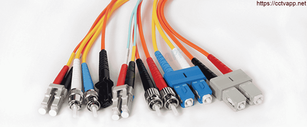
The most common optical connectors today include SC (Subscriber Connector), ST (Straight Tip) and FC (Fiber Connector) standards. In addition, small-form-factor standards such as LC (Lucent Connector) standards are also used for the purpose of saving connection space, especially in environments where space is always lacking. data center. MPO (Multi-Fiber Push-On) is also an increasingly popular connection standard, used in high-density environments with each connector MPO contains up to 12 fibers or more.
Each design has its own advantages and disadvantages, so when choosing a connector, it is necessary to consider important factors such as: application, speed of data transmission support, training requirements for construction workers. about fiber types (singlemode and multimode fiber require different connectors). This article will provide an overview of the characteristics and features of common connector types, helping users make the right choice to optimize network performance.
1. The role of the connector
- The connector is used to connect two optical fibers together, allowing light to pass from one fiber core to the other, or to connect the fiber to an optical signal transmission device. In order to achieve a good connection with low loss, the two fiber cores must be in straight contact and the optical connector surface must be well cared for, free of dust and debris, debris or scratches. scratch.
- It is easier to align two multimode fiber cores (large core diameter) than singlemode fiber. Singlemode connection requires stricter tolerances, connector surfaces must be handled with more care. A stain, scratch or any defect on the fiber surface directly affects the connection performance.
2. Constructing a connector
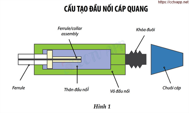
- A connector has the main components as shown in figure 1. The front ferrule is designed to support the fiber cores in contact in alignment, limiting connection loss. This ferrule is held by a collar assembly on the inside of the connector body, pushing the ferrule head forward to make good contact when connecting the two connectors or connecting to the device. .
- In addition, at the end of the optical connector, there is usually a part that increases the resistance to twisting and the load when pulling the cable. At the same time, the protective plastic end of the connector also helps to limit bending when connecting the cable to the device, minimizing optical signal loss.
- It is important to read the specifications. specifications from the manufacturer and compare the expected application’s connection performance. In addition, factors such as the size or type of connection cable should also be considered to select the appropriate product code.
3. Performance issues
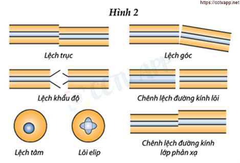
- For a good connection, the fiber cores need to be connected in a straight line and with good surface quality. In the left corner of Figure 2, it can be seen that when two optical fibers are off-axis, part of the light will be lost out, causing signal loss, reducing bandwidth and reducing the transmission distance of light in the optical fiber.
- Connector misalignment is also a case to consider (in the upper right corner of figure 2). Connector misalignment can be avoided by using a PC (Physical Contact) ferrule surface connector. These ferrules are designed to keep the fiber in a straight position when connected, and to help reduce the risk of gaps in the contact surface between the two connectors.
- Two fiber apertures. Mismatch is also the cause of light loss. This error can be caused by connecting different types of optical fibers or by different manufacturers. Thanks to the technological development and improvement of fiber optic cable manufacturers, some other problems such as different core diameters, non-concentricity, elliptical cores or different cladding diameters have disappeared. more.
4. Caring for the connection surface
- Connection surface plays a critical role in optical connection performance. After the head press is performed, it is necessary to sand the connector surfaces to remove stains and defects.
- This process is usually done in the factory, but there are a few types of connectors that need to be ground in the field. This should be done on a soft pad and suitable abrasive paper. The grinding technique is also quite special with the figure-eight motion operation, to evenly grind all corners of the optical connector.
- A common type of optical connection surface is the UPC (Ultra Physical) Contact), providing high connection performance. APC (Angled Physical Contact) is also a common connection type with an 8 degree beveled surface. The APC model limits light reflection at the contact surface, helping to reduce loss on the fiber optic line. This type of connector is commonly used in telecommunications environments and television applications.
- Temperature issues also need to be given due attention. In harsh environments with temperatures ranging from -40°C to 85°C, optical fibers and ferrules can shift and change shape, resulting in reduced connection performance.
5. Performance requirements
- The ANSI/TIA-568-C.3 standard defines the performance of optical connectors used in structured cabling. Optical loss is the most important parameter used to measure performance and is a measure of field-constructed connector acceptance. Although the standard defines a maximum limit for the optical loss rating of 0.75 dB per pair of connectors (single coupling), more stringent specifications may be required depending on the application.
- Reflection, also known as Return Loss, is limited to a minimum of 20 dB for multimode fiber and 26 dB for singlemode fiber. To reduce the reflectance, it is necessary to use the APC connector surface type. The operating temperature range for optical connectors is also defined in the TIA 568-C standard, from -10°C to 60°C, capable of withstanding moisture, impact and other types of twisting stresses. twist and bend. To understand this requirement, consult the manufacturer’s documentation regarding the limits for the product.
6. Optical connector selection
On the market today there are dozens of types of connectors, this article only focuses on common standards, but will also cover connectors such as LC and MPO that are being used as a trend in the environment. specific field, support high speed and save space.
- ST: is a screw-in connector that has been used for many years for local area networks with applications supporting 10Base-F and 100Base-F. Today, STs are no longer common, but they can be easily found in the millions of connections that have been installed in older networks. ST connector uses a 2.5 mm ferrule with a typical loss of 0.25 dB.
- SC: is a connector that uses the plug/unplug method when connecting . Ease of use and high performance, SC connectors are among the most popular, in networks running Gigabit Ethernet applications. The SC connector also uses a 2.5 mm ferrule and a typical loss of 0.25 dB.
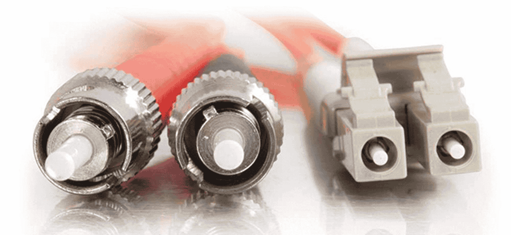
- LC: is a compact sized connector (SFF) only half the size of the SC head, using a 1.25 mm ferrule, 0.25 dB normal loss.
- MPO: is a high density connector, containing the same When there are multiple fiber connections, the connection method is still the same as the SC and LC connectors. Each MPO connector can hold from 4, 6, 12 to 24, 48 or even 60 fibers. Due to its complexity and high precision requirements, this type of connector is currently only pre-punched by the manufacturer. User must place order with given length but head press cannot be done on site.
7. Terminal connection method
- Over the years of developing fiber optic connector technology, manufacturers have introduced many fiber optic end connection methods. The choice of end-to-end connection method often depends on the skill of the builder, available tools or simply preference. Some methods have differences in optical performance, while others are easy to use, saving time and labor.
- There are four basic methods commonly used including including: grinding the optical tip, heat welding (also known as arc welding), mechanical welding and optical tip pressing.
- Grinding the optical tip – this method has been used since the 1980s, when the end Fiber optic connectors began to evolve, and are still in use due to their low loss, reliability, and very competitive cost. This method has the disadvantage of being complicated and time consuming to remove adhesives during construction. At the same time, the quality of the connector is also highly dependent on the skill of the operator, so it needs to be trained and supervised carefully.
- Heat welding – uses a pre-punched fiber optic cable at one end. (pigtail), using the high temperature of the machine to melt and bond the joint. The advantage of this method is that the connector is pre-ground by the manufacturer, which supports connections with low loss and reflection. However, the disadvantages are high equipment cost, need to have a power source in the field to supply welding equipment, high requirements for training and skill training in machine use.
- Mechanical welding– also uses pigtails as heat welding but without the use of welding equipment. This involves cutting and stripping the ends of the fibers with specialized tools, and then holding them together using a component known as a mechanical splice. This method is implemented quickly, using few tools, and the training time is short. However, the high cost of materials, greater loss than the heat-welded method is also a factor to consider.
- Optical head press – unlike previous methods, the connector is pre-grinded. by the manufacturer but does not come with a short length of fiber like a pigtail. The installer only needs to strip and cut the fiber with a special tool, then thread it inside the connector, using the appropriate set of press tools to lock the fiber into the optical connector. Easy and fast operation, capable of performing in narrow spaces, high positions. The disadvantage of this method is the high cost of materials, higher loss than heat welding and the inability to reuse when the tip is faulty.
8. Cleaning and acceptance
- There have been many articles in previous issues that mentioned the importance of cleaning the optical connector, so this article will not go into depth about cleaning methods, except to reiterate It is necessary to clean the connector surface properly using specialized tools and solutions. Because dirt, debris or oil stains from the operator’s fingers all seriously affect optical performance.
- Once completed, the fiber network system should be tested and accepted. . The most common way is to measure optical loss with specialized meters. However, this measurement only gives attenuation data on the entire cable line, but does not provide detailed loss parameters on each connector.
- When the loss exceeds the allowable limit and the measurement results are not accepted, the constructors will be confused because they do not know where the error occurs, especially with fiber optic lines. many joints. In that case, it is necessary to use an OTDR measuring device to determine the distance to the fault point, determine the loss and quality of each coupling, thereby reducing the time spent fumbling and replacing the connectors in vain.< /li>
Conclusion
The fiber optic network system is increasingly developing, leading to the optical connector technology also making great strides with many designs on the market. As the network system moves towards the trend of high density and application speed, the connector market will also move towards smaller connector models such as LC or multi-fiber integrated connectors such as MPO.
To meet increasingly tight loss limits for applications such as 40 GbE or 100 GbE, technicians must follow the manufacturer’s procedures including inspecting and cleaning all all connectors before making the connection. This approach will ensure the performance, quality and reliability of the fiber optic cabling system.
Thanks for following this post!!!